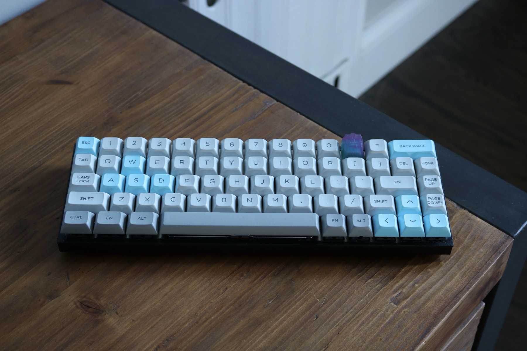
In 2016, I built a keyboard because nobody sold the obvious keyboard.
I wanted something as small as a 60%, except with arrow keys, because I use arrow keys and pretending they belong on a function layer does not make them disappear. A tenkeyless board had the keys I wanted, plus a bunch of keyboard sprawling off to the right where my mouse was supposed to go.
The keyboard market had decided that compactness and navigation were incompatible desires.
Fine. I had a soldering iron.
A 60% With One More Column
I spent most of a week moving rectangles around in Keyboard Layout Editor before buying a single part. This was a good trade. Moving a key in a browser is free. Moving one after soldering sixty-eight switches is considerably less free.
Naturally, my first drafts were too clever. I tried a 40% grid, then a 50%, and kept discovering that I had banished some key I use constantly to a function layer.
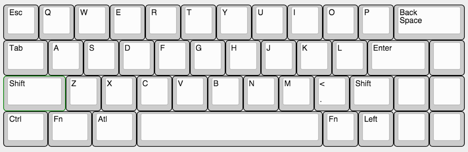
Eventually I stopped pretending the number row was optional. The final layout was a standard 60% with one extra column bolted onto the right edge and an arrow cluster stolen from the bottom-right corner. Sixty-eight keys. Five rows. Fifteen columns.
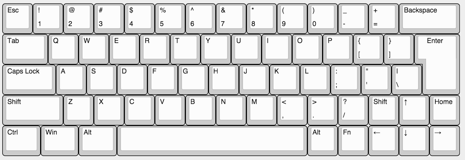
That extra column was the whole idea. Home, Page Up, Page Down, and the arrow keys lived there. My right hand could reach them by moving about one key width instead of crossing a number pad I never used.
I had designed the perfect keyboard. Now all I had to do was manufacture it at my desk.
The Matrix
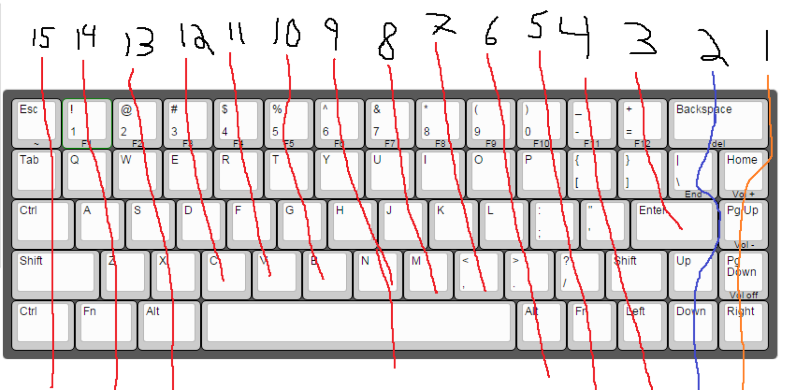
A keyboard controller does not have sixty-eight pins. The switches have to sit in a matrix: the firmware drives one row at a time, reads the columns, and works out which switches are closed.
There is a fun electrical problem hiding in this otherwise simple arrangement. Press the wrong three keys and current can sneak backward through the switches, causing the controller to report a fourth key that nobody pressed. This is called ghosting. The fix is one diode per switch, all facing the same direction.
Sixty-eight switches meant sixty-eight diodes. There is no software abstraction that gets you out of this part.
Before wiring anything, I printed the layout, numbered every column, and traced the runs with a pen. It looked primitive because it was primitive. It also saved me from trying to debug a rat's nest from memory.
Building the Thing
The switches snapped into a 1.5 mm aluminum plate with a 14 mm square opening for each one. Brass standoffs held the plate above the desk and gave the case something to bolt to.
Nothing was glued. This felt important at the time. If a switch failed, I wanted to be able to pull it out, although doing so would still require desoldering the diode attached to it. "Repairable" is a flexible term when you build the product yourself.
The rows were each made from one length of solid-core wire running across the board. I stripped short windows in the insulation wherever a switch needed to connect instead of cutting sixty-eight little jumpers. Each diode bridged a switch to its row bus. The colored wires formed the columns and converged on the controller.
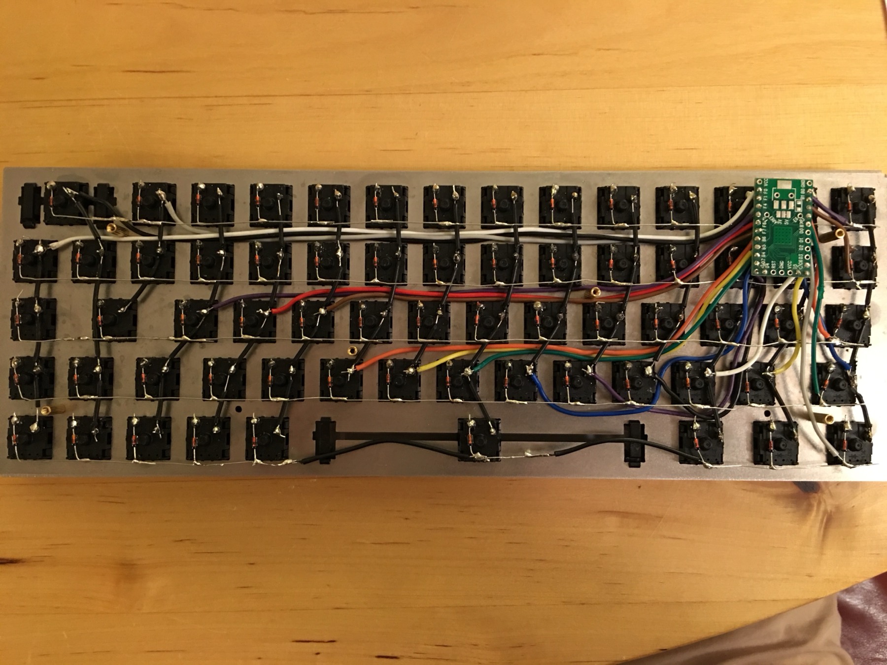
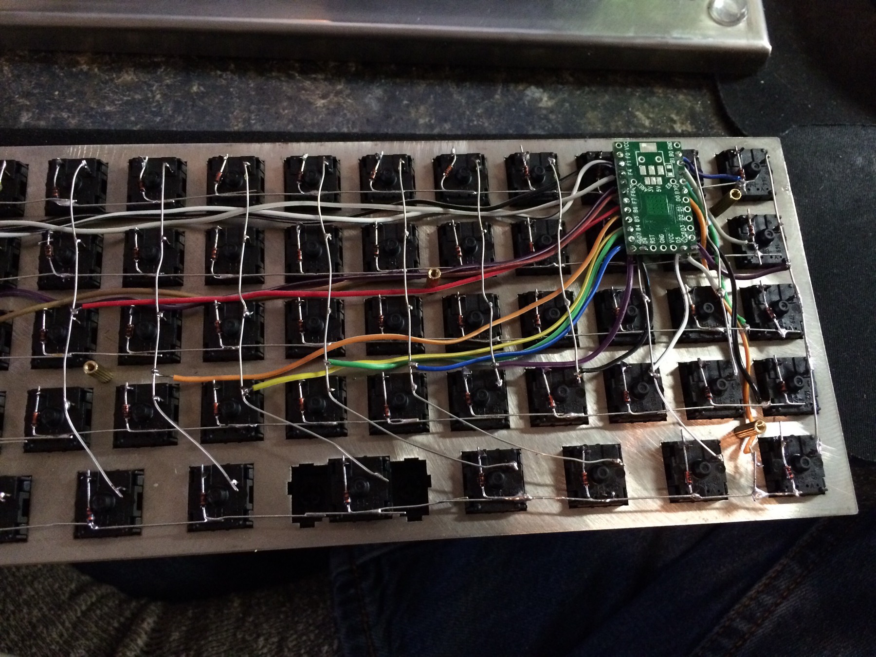
I soldered it over three evenings. The first row took an hour. By the last row I was down to fifteen minutes: tin the leg, tin the wire, touch them together, count to two, move on.
There is something deeply satisfying about getting visibly better at a physical skill over the course of a project. Code does not leave sixty-eight shiny little receipts proving that you learned something.
The Controller
The brain was a Teensy 2.0: an ATmega32U4 running at 16 MHz with native USB. It had twenty-five usable I/O pins, so fifteen columns and five rows fit with five pins to spare.
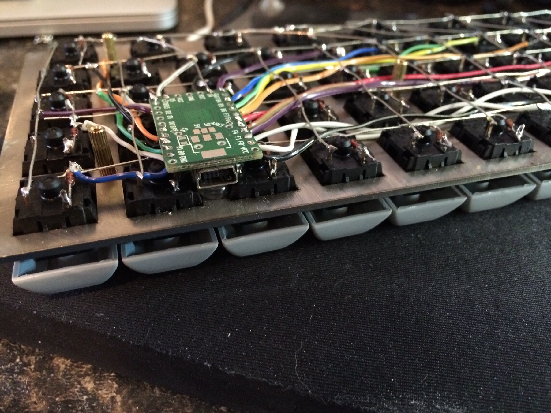
I put it in the top-right corner, with the USB port facing through a slot in the back. That was where the extra navigation column left the most room, and it kept the column wires from having to cross the entire board.
The bundle was still ugly. Fifteen columns and five rows converging on one tiny board means twenty wires arriving at the same square inch. At some point cable management becomes cable acceptance.
Writing the Firmware
I started with the Planck firmware, the most readable open keyboard firmware I could find at the time. It expected a 4x12 ortholinear grid, so the first task was explaining what I had actually built.
The pin map was the hardware description:
/* key matrix size */
#define MATRIX_ROWS 5
#define MATRIX_COLS 15

#define COLS (int []){ F1, F0, B0, C7, F4, F5, F6, F7, D4, D6, B4, D7, B5, B6, D5 }
#define ROWS (int []){ D0, D1, D2, D3, C6 }

/* COL2ROW or ROW2COL */
#define DIODE_DIRECTION COL2ROW

/* Set 0 if debouncing isn't needed */
#define DEBOUNCE    5
DIODE_DIRECTION had to match the direction of every diode I had just soldered. If it did not, the keyboard would look completely dead, with no error message helpfully suggesting that I inspect all sixty-eight of them.
The keymap was a two-dimensional array mirroring the physical grid. This was the pleasant part of writing the firmware: the keyboard layout stopped being something I had to shop for and became a source file I could change.
const uint16_t PROGMEM keymaps[][MATRIX_ROWS][MATRIX_COLS] = {
  [0] = {
    {KC_ESC,  KC_1, KC_2, KC_3, KC_4, KC_5, KC_6, KC_7, KC_8,    KC_9,   KC_0,    KC_MINS, KC_EQL,  KC_BSPC, KC_HOME},
    {KC_TAB,  KC_Q, KC_W, KC_E, KC_R, KC_T, KC_Y, KC_U, KC_I,    KC_O,   KC_P,    KC_LBRC, KC_RBRC, KC_BSLS, KC_PGUP},
    {KC_LCTL, KC_A, KC_S, KC_D, KC_F, KC_G, KC_H, KC_J, KC_K,    KC_L,   KC_SCLN, KC_QUOT, KC_ENT,  KC_NO,   KC_PGDN},
    {KC_LSFT, KC_Z, KC_X, KC_C, KC_V, KC_B, KC_N, KC_M, KC_COMM, KC_DOT, KC_SLSH, KC_RSFT, KC_NO,   KC_UP,   KC_NO},
    ...
  },
Layer one held everything a 60% normally gives up: the function row on the number keys, media and volume controls in the right column, and Delete where Backspace lived.
  [1] = {
    {KC_GRV,  KC_F1,   KC_F2,   KC_F3,   ... KC_F12, KC_DELETE, KC_TRNS},
    {KC_TRNS, ...                                    KC_END,    KC__VOLUP},
    {KC_TRNS, ...                                    KC_TRNS,   KC__VOLDOWN},
    {KC_TRNS, ...                                    KC_TRNS,   KC__MUTE},
  }
KC_TRNS means transparent: use whatever the key does on the layer below. Without it, every layer would have to repeat the entire keyboard.
Of Course It Did Not Work
The board enumerated over USB. The operating system recognized it. One entire column did absolutely nothing.
I spent an evening rereading the keymap because I am a programmer and therefore assumed the metal was correct and the software was wrong.
It was a cold solder joint on a column wire, three switches from the end. The joint looked fine and was mechanically attached, but it was electrically open. Once I finally picked up a multimeter, continuity mode found the problem in about ninety seconds.
When you build both the hardware and the software, you lose the comforting ability to assume the bug is in the other half.
The Finished Keyboard
Grey and off-white PBT keycaps made the keyboard look like an object instead of an ongoing incident. I used blue caps for the modifiers and navigation column so I could find them without reading the legends, then put the plate into a black case that hid all the wiring.
Here it is next to the Poker II that made me want to build it:

The hand-wired board had the arrow keys, Home, Page Up, and Page Down that the Poker II was missing. It was only one column wider. The firmware was mine. On paper, I had won.
In reality, the keyboard kinda sucked.
I never really used it. The professionally manufactured keyboard was, unsurprisingly, a better keyboard. Mine cost more by the time I counted the plate, switches, keycaps, Teensy, and the soldering iron I did not previously own. It took days to build and rewarded me with something I did not particularly enjoy typing on.
But I loved making it.
That was the actual point, even if I did not know it when I started. I learned how a keyboard matrix worked because I had to wire one. I learned how ghosting worked because I had to solder sixty-eight diodes to stop it. I learned to debug the metal instead of endlessly staring at the code. At the end, I plugged in a completely ridiculous object I had designed and assembled at my desk, and it typed.
Not every project needs to become a good product. Sometimes the fun part is finding out that you can build the thing at all.